From art to science – the development of the PCB

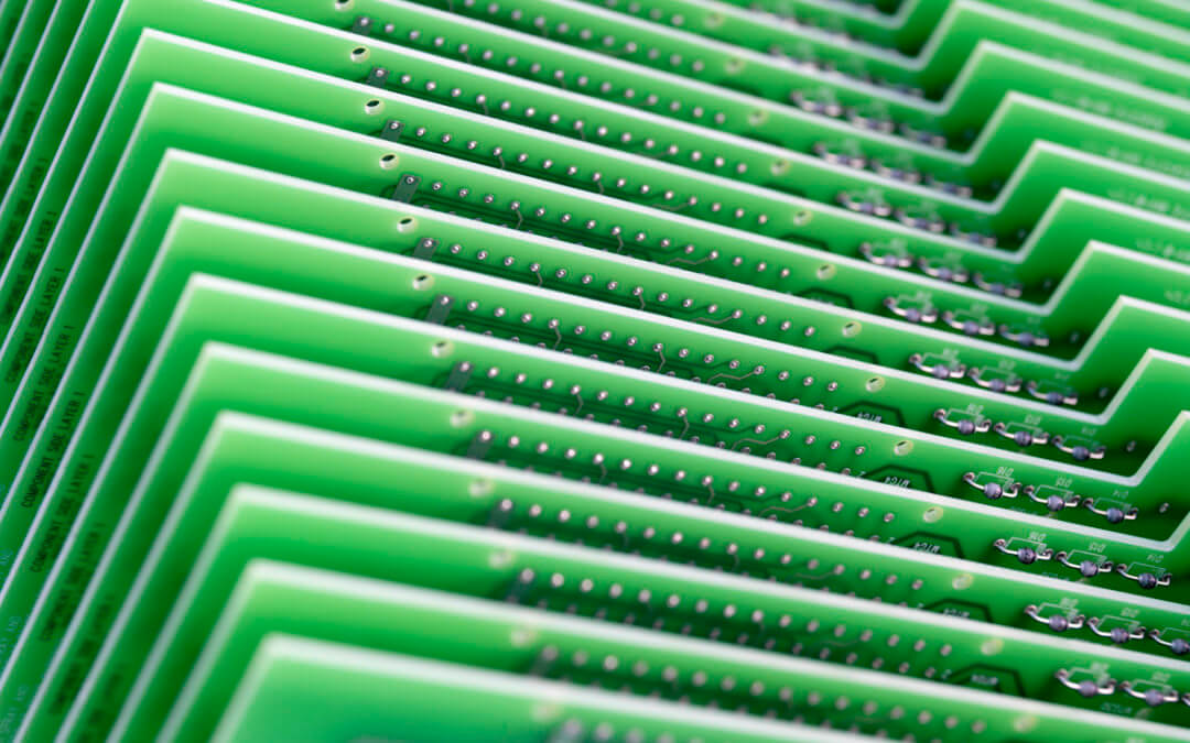
From-art-to-science-1080x675

We recently outlined the evolution of the PCB after it emerged to replace point to point connections on a chassis in the years following World War II.

Here we’d like to trace the key moments in recent years that our brief history did not allow us space for.

As we chart how the manufacture of PCBs transformed from an art to a highly-specialised science we pinpoint five decisive moments that have kick-started their development in recent decades.

In the beginning

The earliest PCBs were very much works of art.

Etched by hand, they owed more to technology from artwork reproduction than to high tech.

To create these circuits copper-clad boards were used. The artwork was hand-drawn, and once the track layout was defined, it was printed onto the board as an etch-resist mask. Acid was next used to etch away the exposed copper before another chemical removed the etch resist.

Although we would still recognise the circuit board produced today, the process of producing it had its roots squarely in methods that had long been used in printing and artwork reproduction.

These processes have changed much since the tech breakthroughs and the manufacturing and electronic development that came to a head in the 1990s.

Here are just five of the ways that PCB manufacture was transformed from an art to a science.

The multilayer breakthrough thanks to via

It was in the 1990s that the use of multilayer surface boards became more frequent, allowing for greater complexity and speed.

The inevitable reduction in size of PCBs allowed them to be incorporated into a wider range of designs and devices.

What  the introduction of blind via and buried via permitted was connection on different layers through copper-plated holes functioning as an electrical tunnel through the insulating substrate. In the past connection through layers had been allowed using plated thru-barrels, but these created an obstacle to connections to every other layer.

The result, following the introduction of via technology in 1995, was the production of High-Density Interconnect (HDI) PCBs.

These could accommodate a much denser design on the PCB and allowed the use of significantly smaller components. With multilayer HDI PCBs reliability is enhanced in all conditions, which is why the most common applications for HDI technology are computer, mobile phone components, medical equipment and military communication devices.

Via have continued to evolve, with the recent emergence of micro-via, a specific type of small via which is used on particularly high-layer-count, densely populated PCBs, which are typically performing some form of high-speed number crunching.

Leadless components and the shrinking PCB

As we’ve seen PCBs really started to shrink in the 1990s (and they haven’t stopped since). Alongside the use of micro-vias we also saw the advent of leadless component designs, such as BGAs, uBGAs, chip-scale packages and so on.

These paved the way for integrated circuits with more gates which ushered in the start of successfully embedding memories and Systems on Chip (SoC) together.

Leadless packages save space by keeping the contact points in a matrix underneath the component instead of squeezed side-by-side around their perimeter. This extra space is crucial for applications like mobile devices, tablets and wearables, where every millimetre counts.

However, leadless packages also have a great deal of mechanical strength, so they don’t separate from PCBs as easily. This is thanks to their high contact area to package ratio which allows them to withstand a great deal of pulling and shear forces.

Since leadless devices are suspended on a matrix of underside solder spheres rather that soldered pins around the perimeter, manufacturing and inspection techniques need to be much more sophisticated, but the space-efficiency and reliability benefits are compelling.

Flexible circuits transform PCB designs

It was, again, in the 1990s that flexible circuits really made their presence felt, although their history can be traced all the way back to the birth of the PCB itself.

With the first PCB manufactured by Paul Eisler less than a decade old, we find a published exploration by Cledo Brunetti and Roger W. Curtis in 1947 of creating circuits on flexible insulating materials. Indeed, by the 1950s Victor Dahlgren and Royden Sanders had already made significant advances in actually developing processes that could print and etch flat conductors on flexible base materials.

Today, flexible circuits are produced by mounting electronic devices on flexible plastic substrates (such as polyimide, PEEK or transparent conductive polyester film) or by screen printing silver circuits on polyester.

They offer several advantages for many applications. These include their potential to replace multiple rigid boards, their suitability for dynamic and high-flex applications and their ability to be stacked in various configurations.

You will find them in:

  • Tightly assembled electronic packages, where electrical connections are required in three axes, such as cameras.
  • Electrical connections where the assembly is required to flex, such as folding mobile phones and laptop screen hinges.
  • Connections between sub-assemblies to replace the bulky and heavy wire harness, such as in cars, laptops, rockets and satellites.
  • Electrical connections where board thickness, weight or space constraints are important factors.

The finishes that created new beginnings for the PCB

The range of finishes that have been introduced into PCB manufacture over the last 20 years has also greatly enhanced their suitability for use in a number of applications.

The finish is applied to ensure solderability and to create the base of electronic connection between board and device. But, the correct surface finish selection can also affect PCB reliability – and the introduction of new finishes has greatly enhanced their reliability under a number of different conditions.

  • HASL

The traditional finish is Hot Air Solder Levelling (HASL) but this is now increasingly being replaced by lead-free HASL.

All HASL finishes prevent oxidation from the underlying copper but the process causes high stress on the PCB and this can diminish its long-term reliability. The process is also not suitable for HDI PCBs.

  • ENIG

ENIG (Electroless Nickel Immersion Gold) offers a great alternative – but one that comes with a price tag.

Ideal for fine pitch, flat surfaces, ENIG perfectly suits the modern-day HDI PCB. It can, however, carry undesirable magnetic properties and is prone to a build-up of phosphorous that may cause faulty connections and fractured surfaces.

  • OSP

OSP (Organic Solderability Preservative) is a finish that can be considered for fine pitches, BGA and small components. In addition, it is less expensive than ENIG and highly repairable, but it is difficult to test and has a limited shelf life of six months.

The rise of the exotic substrate

PCB manufacture has over the years gradually settled on the glass epoxy laminate of FR-4 as its preferred material.

There is good reason for this – in terms of performance and affordability – but we have, in recent times, seen the introduction of a number of alternatives. These ceramic and metallic substrates are often suited to specialist applications, such as those requiring performance in conditions of high temperature and high power.

They include:

  • Aluminium
    Used for parts requiring significant cooling, such as power switches and LEDs.
  • Kapton
    A polyimide foil used for flexible printed circuits that is resistant to high temperatures.
  • FR-5
    Woven fiberglass and epoxy offering high strength at higher temperatures.
  • G-10
    Woven glass and epoxy offering high insulation resistance, low moisture absorption and very high bond strength.
  • G-11
    Woven glass and epoxy offering high resistance to solvents as well as high flexural strength retention at high temperatures.
  • RF-35
    Fiberglass-reinforced ceramics-filled PTFE (Teflon) offering good mechanical and high-frequency properties.
  • Polyimide
    A high-temperature polymer offering excellent performance that can be used from cryogenic temperatures to over 260 °C.

The return of the art of the PCB

The diversity of today’s PCB technology requires an artist to create the perfect board for each device, application and customer.

Chemigraphic has the broad expertise and capability in each specialist area to understand and decide which technology and processes will create the right PCB for your requirements and budget.
A short history of the PCB

As PCBs increasingly shrink in size, their capabilities, power and importance continue to grow.

Space travel, the consumer electronics boom and many ground-breaking (and life-saving) medical devices are quite simply unimaginable without the humble PCB.

The world market for blank PCBs exceeded $60 billion for the first time in 2014 – and it’s estimated to reach nearly $80 billion by 2024.

Let’s review how we got here – and where we might be going – with a short history of the PCB.

A short history of the PCB

Point-to-point precursors

Before the development of PCBs, circuits were wired point-to-point on a chassis.

This was usually made from a sheet metal frame with a wooden bottom. Insulators connected the components to the chassis and their leads were connected by soldering.

They worked – but they also left a lot to be desired. They were large, bulky, heavy and relatively fragile, not to mention being incredibly labour-intensive and costly to produce.

Early innovators point to the way forward

At the turn of the 20th century a number of innovations began to pave the way for the PCB – but it would take 36 years for these to coalesce into the PCB as we know and love it.

In 1903 Albert Hanson filed a British patent for a device described as a flat, foil conductor on an insulating board with multiple layers and the next year Thomas Edison experimented with various chemical methods to plate conductors onto linen paper.

By 1913 Arthur Berry was busy in the UK filing a patent that described a print-and-etch method while, across the pond, Max Shoop obtained a US patent for flame-spraying metal onto a board through a patterned mask.

We were getting closer – but there was still no cigar.

The first real breakthrough moment must be awarded to Charles Ducas.

He applied to the US Patent Office in 1927 to protect his method of electroplating circuit patterns. The process he used placed an electronic path directly onto an insulated surface. Copper wires were not yet available for these printed wire circuits, so the first almost-recognisable PCB was made from brass wires.

The music printing industry creates the first PCB

Closely resembling a PCB, Ducas’ electroplated circuits were only intended to be used as a flat heating coil. There was no actual electrical connectivity between board and components, but it was only going to be a matter of time until this was realised.

And it was realised by an Austrian engineer on the run from the Nazis. Working in the English music printing industry, Paul Eisler developed his PCBs partly while in jail as an illegal alien.

It was in 1936 that Eisler first produced a PCB as part of a radio. Eisler’s dream was to use the printing process to allow electronic circuits to be laid onto an insulating base in high volumes. At the time, the hand-soldered circuit wires were error-prone and not easily scalable.

The demands of war led to the PCB’s wider adoption

It wasn’t until 1943 that Eisler’s dream became a reality. In 1943 the USA began using his technology on the scale he envisioned to manufacture proximity fuses for use in World War II.

After the war, in 1948, the US military released their innovations into commercial use and the stage was set for a much wider adoption of PCBs.

Despite this, printed circuits did not become commonplace in consumer electronics until the mid-1950s. It was in the baby boomer years that the auto-assembly process developed by the United States Army Signal Corps allowed for much faster creation of PCBs.

This process was developed by Moe Abramson and Stanislaus F. Danko in 1949. It used component leads inserted into a copper foil interconnection pattern and dip soldering to speed things up.

This concept, complemented by board lamination and etching techniques, remains the standard PCB fabrication process used today. It solved once and for all the time-consuming demands and high costs of through-hole construction, which required holes to be drilled through the PCB for the wires of every component.


Multilayer PCBs and Surface Mount Technology

The rise in popularity of multilayer PCBs with more than two, and especially with more than four, copper planes was concurrent with the adoption of Surface Mount technology (SMT).

This began in the 1960s but it wasn’t until the 1980s that it was fully adopted as standard.

SMT was developed by IBM, and the densely packed components it allowed found their first practical use in the Saturn rocket boosters.

Throughout the 1970s, the circuitry and overall size of the boards were shrinking in size.

Components were mechanically redesigned to be soldered directly onto the PCB surface – and hot air soldering methods helped achieve this.

As components became smaller, they were increasingly placed on both sides of the board, allowing for much smaller PCB assemblies with higher circuit densities.

Surface mounting lends itself well to a high degree of automation, reducing labour costs and greatly increasing production rates.


Gerber and EDA in the 1980s


Despite these developments, many PCBs were still being drawn by hand with a light board and stencils until the 1980s.

The arrival of computers and EDA software, such as Protel and Eagle, was about to completely change the design and manufacture of PCBs.

Today designs are saved as Gerber text files and these coordinates are fed directly into the manufacturing machinery.

The HDI era of the 1990s

In 1995 we saw the first use of micro-via technology in PCB production, introducing the era of High Density Interconnect (HDI) PCBs.

HDI technology allowed for a denser design on the PCB and significantly smaller components. As a result, components can be closer and the paths between them shorter.

This is achieved through the use of blind (or buried) vias or microvias, which offers enhanced reliability and lower costs, especially for multilayer PCBs. HDI technology is particularly favoured for computer, mobile phones, medical and military equipment.

And into the future

Which brings us bang up to date.

But why stop there?

The incredible advances of the last 80 years show no signs of slowing.

In fact, the opposite: Moore’s law is far from being repealed, despite what you may have heard.

Here’s just a few of the forthcoming PCB features that will drive new capabilities and developments.

  • Recent advances in 3D printing, using liquid inks that contains electronic functionalities, are leading to several applications for PCB manufacture.
  • The increased use of integrated circuit chips to deliver millions of tiny resistors, capacitors, and transistors fabricated on a semiconductor wafer.
  • The space-saving benefits and electrical performance benefits offered by package on package (POP) and embedded component techniques
  • Greater environmental awareness is spearheading research into the possibility of adopting PCBs made from paper
  • As medical technology look to create an endless feedback loop between patient, doctor and device flexible circuitry for wearables looks set to drive innovation
  • Photonics and PCB are inching closer and herald efficiency, miniaturisation and flexibility on a scale previously unimaginable, as photons, rather than electrons, are used to route electrical signals.
  • Wave technology may even replace the need for a physical medium to connect components – these are copper-less PCBs for a wireless age

Drawing blanks: our guide sourcing PCB blank boards

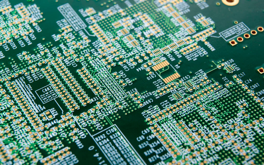
printed-circult-board-1080x675

They say that from small acorns mighty oak trees grow.

In electronics it’s on blank PCB boards that the grandest of designs are etched – and components mounted – to create the mightiest of devices.

In this review, we’re going to talk you through the options you have when you source blank boards for your electronic PCB assembly.

Taking each option in turn, we’ll explore the different supply routes available to you and the benefits that each offers at each stage of production.

Of the factors affecting your choice you will need to consider:

  • Time
  • Cost
  • Quality
  • Availability
  • Regulatory requirements for finished product
  • Performance requirements for finished product
  • Reliability and reputation of supplier

Of course, a very real benefit of working closely with an EMS partner is to take advantage of their expertise in managing the supply chain to meet your requirements and goals. At Chemigraphic our thorough and proactive approach to sourcing ensures you can overcome supply chain challenges and realise your great oaks every time.

Blank board demand

Demand for PCBs – and the blank boards on which they are created – continues to grow.

The world market for PCBs first exceeded the $60 billion mark back in 2014. It is estimated to be touching close to the $80 billion mark by 2024, thanks to a CAGR of 3.1%.

With demand sailing this high, you’d expect some competitive drops in prices for the blank boards – but price is very much dependant on the volumes you are ordering in and the timelines you are working to.

We’ll review later how it can be subject to other factors too.

How to source your supply of PCB blank boards

The three main routes for sourcing blank PCB boards are:

  • Quick turnaround routes
  • Third-party broker routes
  • Direct from overseas manufacturer routes

Let’s take a look at the pros and cons of each of these.

The quick turnaround route

This is usually best-suited to the speed and low volumes demanded during the rapid prototyping <link> of products in the pre-manufacture stage.

Typically, small volumes are required for this, but they are needed very quickly. The need for speed here has tended to mean that UK or European suppliers are used to expedite the orders. But times are changing: as closer relationships are developed with overseas suppliers – particularly based in Special Economic Zones in China – then these are being increasingly used as a quick turnaround option. Delivery times are rapidly dropping and cost savings on even small quantities of blank boards from Asia can be significant.

It is time, and not cost, that remains the main driving force for using quick turnaround suppliers. Ideal for rapid prototyping and proof of concept, they are also be used for unexpected or top-up orders should insufficient stock be held in reserve.

The main drawback of such orders is related to their instant availability. They tend to offer limited technical capabilities (because they are produced so quickly) and come at a higher unit cost (because they are produced in such small quantities).

This makes them unsuitable for more complex or larger volume projects.

The third-party broker route

Using a broker or agent in an offshore location can quickly open out a base of contacts and established relationships with manufacturers and suppliers in that region.

This is an option that tends to be used when first using blank boards from an area or when looking to create an expanded list of trusted suppliers within it.

The obvious benefit offered is that it minimises risk when using a new supply source – the relationship is guaranteed, and the responsibility owned, by the broker.

Brokers can also be useful should a regular supplier’s prices unexpectedly rise or if there are supply shortages from this established source.

As the broker is ordering regularly with suppliers for a large number of customers, there is also the benefit of the reduced costs that their consolidated spend brings.

For medium-volume orders this can represent a very reliable and cost-effective route as it delivers considerable cost-savings without the additional requirements – and hidden costs – involved in managing the entire process directly.

It should be noted, however, that a typical broker fee for acting as the ‘middle-man’ is usually around 20%, and that the additional links created in the supply chain can cause delays and create complexities.

The direct route

Accessing offshore, low-cost suppliers directly is possible thanks to the range of contacts your EMS partner brings to the table.

By sourcing offshore directly a lower price can be achieved. It is critical, however, that you understand the dynamics of the supply chain involved and have developed established relationships with trusted suppliers in these offshore locations.

With no broker involved there is an instant saving of around 20% to be realised and, additionally, you gain direct control over the source and the process. With less links involved it is often easier to reach decisions and resolve any issues much quicker.

This option is best suited to those high-volume projects where engineers’ time and extra work is required as it is only then that the additional work involved in using the direct route can be justified.

The additional work here includes:

  • Managing and owning every detail of the process
  • Co-ordinating delivery and logistics
  • Understanding the conditions that affect the capabilities of the local market
  • Establishing relationships with each supplier used
The blank board through the crystal ball

Blank boards – like any other component or material – used in electronic manufacture can be highly responsive to events throughout the global economy.

In recent times we are witnessing the uncertain effects of Brexit threaten our ability to 100% rely on a stable, continued European supply at a consistent price.

Elsewhere, the effects of Donald Trump’s trade war and war of words with China may have unforeseen circumstances – and China is a critical part of our supply chain.

Our CEO, Chris Wootton outlines some more thoughts on this in a recent EPDT article, where he comments:

‘As an EMS, the benefits that China offers in terms of manufacturing and sourcing electronic components are simply too extensive to ignore.

We opened our new sourcing office in Shenzhen in January, and already, our customers are benefiting from the higher volumes and lower costs of component parts thanks to the improved access to China’s pricing structures we can now offer.’

In terms of future trends it should be noted that:

  • The Chinese government has steadily increased the level of minimum wage since 2007 – and this rise has been most marked in areas where most electronic parts and supplies are manufactured (such as Shenzhen and Shanghai).
  • India, Malaysia, Thailand and Vietnam are increasingly competing for larger orders – but what they save in labour costs is still at present off-set by higher material costs for smaller orders.
  • The rise in cost of copper foil will push prices up regardless of where blank boards are sourced. This is a result of limited global copper foil productivity being hit by increasing demand from the production of electrical vehicles (which use this in their lithium batteries).

As ever, OEMs with a trusted EMS partner can achieve the flexibility to successfully navigate the changes, breaks and risks inherent in any global supply chain.

And together we will ensure we grow mighty oaks from the small acorns on our BOM.